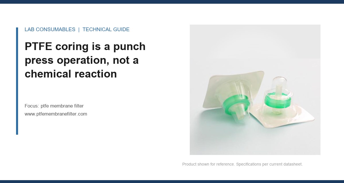
A 96-position autosampler run on a dissolution batch failed at vial 41. The needle bent 0.7 mm off axis when it hit a PTFE plug that had been punched out of the filter and wedged inside the cap septum. The lab found the same failure in three of the next five runs before anyone pulled a filter from the lot and looked at it under a loupe. PTFE membrane filter coring, fragments and needle damage diagnosis starts with recognizing that the debris is not random. It is a mechanical signature left by a specific set of dimensions and forces.
A PTFE membrane filter cores when the needle tip acts like a hollow punch against a membrane that is already under tension from the housing. The needle enters through the septum, passes the septum face, and contacts the PTFE layer. If the needle bevel is not sharp enough or the membrane is not supported directly under the entry point, the tip cuts a circular plug instead of piercing a slit. That plug, typically 0.4 to 0.8 mm in diameter depending on needle gauge, rides up the needle lumen or drops into the vial.
I have seen labs blame the filter lot when the real problem was a needle that had been through 800 punctures on a 22-gauge specification. PTFE does not dull needles quickly, but polypropylene housing flash and septum silicone do. Once the bevel rolls over, it stops slicing and starts stamping. The force required to push a dull 22-gauge needle through a 0.45 µm PTFE membrane can rise from 1.8 N to over 4 N. At 4 N, the membrane fails by shear, not by controlled puncture. That shear failure is what produces a clean plug.
The mechanical sequence is specific. The needle tip contacts the membrane. The membrane stretches until the local stress exceeds the tensile yield of the expanded PTFE node-and-fibril structure. A sharp tip creates a tri-lobed tear that opens and reseals around the needle shaft. A dull or hooked tip creates a circular cut because the force is distributed evenly around the bevel circumference. The cut plug separates because PTFE has low elongation at break along the machine direction of the membrane, often 50 to 150 percent depending on pore size and thickness. That is low enough to snap cleanly under a stamping load.
Read the debris under a loupe before you blame the filter lot
You need a 10x loupe and a clean white background. Dump the contents of a suspect vial onto a glass slide. Let the liquid evaporate if it is aqueous. What you see tells you more than any certificate of analysis.
A true PTFE core is a disc with one smooth face and one rough face. The smooth face is the side the needle tip contacted. The rough face is the side that tore away from the membrane sheet. The disc is usually flat, not curled, because PTFE has memory and the plug was cut under compression. If you see fibers attached to the disc edge, the membrane was not fully sintered or the needle was pulling as it exited. If you see a crescent instead of a full disc, the needle bevel was partially dull and the plug tore loose on one side.
Septum debris looks different. Silicone fragments are irregular, elastic, and often roll into a ball. PTFE-coated septum faces can delaminate and produce flakes, but those flakes are thinner than a membrane core and have a different surface texture. A PTFE membrane core has visible node structure under 20x magnification. A septum flake does not.
Measure the plug diameter. A plug from a 22-gauge needle is 0.71 mm outside diameter. A 23-gauge needle produces a 0.64 mm plug. A 0.45 mm plug means the needle was 26-gauge or the plug came from a pre-slit septum, not the membrane. If the plug diameter is larger than the needle ID, the plug was compressed during cutting and expanded after release. That is normal. If the plug diameter is smaller than the needle ID, the plug was shaved by the needle wall, which means the needle had a burr on the inside edge.
What a burr on the needle ID does to a PTFE membrane
A burr on the inside edge of the needle lumen acts like a second cutting edge. As the needle passes through the membrane, the burr shaves a ring of PTFE from the plug and leaves micro-fragments in the needle. Those fragments are 10 to 50 µm and are easy to miss under a 10x loupe. Under 30x, they look like fine white dust. They accumulate in the needle over 20 to 50 injections and then release into a sample unpredictably. That is the failure that drives analysts to replace needles, injectors, and liners before they check the filter.
The fix is to inspect needles under a stereo microscope at 20x after every 100 punctures. Look at the bevel heel and the lumen edge. A rolled heel is visible as a bright line. A lumen burr shows as a jagged shadow inside the opening. Replace the needle when the bevel heel is no longer crisp, not when it visibly bends. For a 22-gauge needle used on 0.45 µm PTFE, that is usually 300 to 500 punctures depending on septum hardness and autosampler speed.
Needle and guide dimensions that cause PTFE coring
The interaction between needle gauge, needle point style, and filter housing geometry decides whether you get a clean slit or a punched plug. Three dimensions matter more than any others.
First, the needle point style. A standard bevel needle, 12 to 15 degrees included angle, pierces PTFE cleanly when sharp. A blunt-tip needle, 90 degrees, will core every time on an unsupported membrane. Some autosamplers ship with blunt-tip needles for pre-slit septa. If you pair that needle with a non-pre-slit PTFE filter, you will see coring within 10 punctures. I have seen this exact mismatch on a GC autosampler that was moved from a method using pre-slit caps to a method using PTFE membrane filters.
Second, the needle gauge. A 26-gauge needle has a wall thickness of 0.15 mm and an ID of 0.26 mm. The thin wall cuts PTFE easily but the small ID means any plug that does form is more likely to clog the needle completely. A 19-gauge needle has a wall thickness of 0.28 mm and cuts a larger plug. The larger plug is less likely to clog the needle but more likely to fall into the vial and contaminate the sample. The sweet spot for most HPLC and GC autosampler work is 22 or 23 gauge because the wall is thick enough to resist bending and the ID is large enough to pass a small plug without clogging.
Third, the guide hole in the filter housing. The guide is the opening in the cap or housing that aligns the needle with the membrane. If the guide ID is more than 0.3 mm larger than the needle OD, the needle can drift off center and contact the membrane at an angle. An angled contact increases the effective cutting area and raises the chance of coring. The guide ID should be 0.1 to 0.2 mm larger than the needle OD. For a 22-gauge needle with 0.71 mm OD, the guide should be 0.8 to 0.9 mm ID. If you measure 1.1 mm or more, the guide is worn or the housing was molded out of tolerance.
Housing support under the membrane changes everything
A PTFE membrane filter cores less when the membrane is fully supported by a rigid backing plate or a sintered frit directly under the needle entry zone. Unsupported membranes, common in low-cost syringe filters, stretch under needle load and fail by shear. Supported membranes fail by controlled puncture because the backing plate limits deflection.
The difference is measurable. A 25 mm syringe filter with a 0.45 µm PTFE membrane on a polypropylene support ring will typically survive 50 to 80 needle punctures at one entry point before coring begins. The same membrane on a full sintered polyethylene frit will survive 200 to 400 punctures at the same point. If your method requires multiple draws from the same filter, specify a frit-backed housing. If you are already using one and still see coring, the needle is the problem, not the filter.
Case 1: the 0.8 mm plug that stopped a GC sequence
A contract lab running EPA 8270 semivolatiles on a GC-MS system started seeing random peak area drops of 30 to 60 percent on internal standards. The drop appeared in one injection out of every 15 to 20. They replaced the liner, the gold seal, the column, and the syringe. Nothing changed. When they pulled the autosampler needle and pushed solvent through it, they recovered a white plug 0.8 mm in diameter from the lumen. The plug was PTFE, confirmed by FTIR. The source was a 13 mm syringe filter with 0.2 µm PTFE membrane that the analyst used to filter extracts before injection.
The needle was a 23-gauge cone-tip style with 0.64 mm OD. The filter housing had a guide ID of 1.0 mm, leaving 0.36 mm of lateral play. The cone tip, combined with the loose guide, allowed the needle to hit the membrane at a 5 to 8 degree angle. That angled contact cut a plug instead of piercing. The fix was to switch to a 25 mm filter with a frit-backed PTFE membrane and a guide ID of 0.75 mm. The lab also replaced the needle. The peak area drops stopped on the next sequence.
Case 2: the 0.45 mm fragments that passed a visual check
A pharmaceutical QC lab running a dissolution method with HPLC analysis found an unknown peak at 2.3 minutes in roughly one sample per 96-well plate. The peak area was small, 0.5 to 2 mAU, but it failed the method’s impurity specification. The analyst filtered samples through a 0.45 µm PTFE syringe filter before injection. Visual inspection of the filters showed no damage. The septa looked intact.
We pulled the needle and flushed it with methanol onto a 0.2 µm silver membrane. Under a stereo microscope at 30x, the silver membrane showed white fragments 10 to 40 µm long. The fragments were PTFE, not septum material. The needle had a burr on the lumen edge, invisible to the naked eye. The burr was shaving micro-fragments from the PTFE membrane on every puncture. The fragments accumulated in the needle and released intermittently. The fix was to replace the needle and institute a 100-puncture inspection interval. The lab also moved to a PTFE membrane filter with a pre-slit septum to reduce puncture force.
Decision checklist: diagnose the source in 15 minutes
Run this checklist before you order a new filter lot or replace an autosampler. It separates needle problems from housing problems from membrane problems.
- Measure the plug diameter. If it matches the needle ID within 0.05 mm, the needle cut the plug. If it is smaller, a burr shaved it. If it is larger, the plug compressed and re-expanded.
- Check the needle bevel under 20x. A crisp bevel reflects light evenly. A rolled heel shows a bright line along the cutting edge. Replace if the heel is rolled more than 0.05 mm.
- Measure the guide ID. Use a pin gauge set. If the guide ID exceeds the needle OD by more than 0.3 mm, the needle can drift and cut at an angle.
- Check the membrane support. Hold the filter up to a light. A frit-backed housing shows a uniform porous disc under the membrane. An unsupported housing shows the membrane sagging into the outlet channel.
- Count punctures per filter. If you exceed 50 punctures on an unsupported 25 mm filter or 200 on a frit-backed filter, coring probability rises sharply.
- Flush the needle. Push 1 mL of methanol through the needle onto a white 0.2 µm membrane. Inspect at 30x. Any white fragments mean the needle is shaving PTFE.
Needle point style vs. PTFE membrane: what actually works
Not all needle points are equal on PTFE. I have tested standard bevel, cone tip, blunt tip, and side-port needles on 0.2 and 0.45 µm PTFE membranes.
| Needle point style | PTFE coring tendency | Punctures before failure on unsupported 25 mm filter | Best use |
|---|---|---|---|
| Standard bevel, 12-15° | Low when sharp | 50-80 | General HPLC and GC autosampler work |
| Cone tip | Moderate to high | 20-40 | Avoid on unsupported PTFE; use only with frit-backed housings |
| Blunt tip, 90° | Very high | Under 10 | Pre-slit septa only; never use on non-pre-slit PTFE |
| Side-port | Low | 60-100 | Reduces plug ingestion; check side-port hole for PTFE buildup |
The table assumes a 22-gauge needle and a 25 mm filter. Smaller filters, 13 mm, fail sooner because the membrane has less unsupported area to distribute the puncture load. A 13 mm unsupported PTFE filter will core after 15 to 30 punctures with a standard bevel needle. If your method uses 13 mm filters, specify frit-backed housings or accept that you will replace filters more often.
Puncture force and autosampler speed: the two levers you can adjust today
Autosampler needle speed is a setting most labs never touch. The default is often 50 to 100 mm/s. At 100 mm/s, the needle hits the membrane with enough kinetic energy to initiate shear failure before the PTFE can stretch and tear. Slowing the needle to 10 to 20 mm/s gives the membrane time to deform elastically and reduces coring. The tradeoff is cycle time. On a 96-vial run, slowing from 100 to 20 mm/s adds roughly 3 to 5 minutes. That is cheap insurance compared to a failed sequence.
Puncture force is the other lever. A sharp 22-gauge needle on a 0.45 µm PTFE membrane should require 1.5 to 2.5 N. If you measure 4 N or more, the needle is dull or the membrane is unusually thick. Some PTFE membranes are cast at 150 to 200 µm thickness for chemical resistance. Those thick membranes core more easily because the needle must displace more material. If you are using a thick PTFE membrane and seeing coring, switch to a 100 µm membrane. The chemical resistance is the same; the puncture force drops by 30 to 40 percent.
For regulated work, check the method before changing membrane thickness. USP 621 and EPA SW-846 methods often specify pore size, not thickness. But some in-house methods do specify a membrane thickness or a filter part number. Changing thickness without a method update will fail an audit. The U.S. EPA SW-846 test methods for waste and materials are explicit about filter pore size for extract cleanup. Thickness is usually not controlled, which gives you room to move.
When to suspect the vial, the cap, or the septum instead of the filter
PTFE membrane filter coring is often blamed for problems that actually originate at the vial closure. A septum that is too hard, too thick, or not pre-slit will dull the needle faster than any membrane. Once the needle is dull from the septum, it cores the membrane. The filter is the victim, not the cause.
Check the septum hardness. A Shore A 45 to 55 silicone septum is standard for autosampler work. A Shore A 70 or harder septum, common in some PTFE-faced butyl septa, will roll a needle heel in 100 to 200 punctures. If your 2 mL vial uses a hard butyl septum and you filter through PTFE, replace the needle more often or switch to a softer septum.
Also check the cap torque. An over-tightened cap compresses the septum and increases puncture force. A cap torqued to 0.6 N·m is typical. At 1.0 N·m or higher, the septum bulges into the vial and the needle must punch through more material. That extra force transfers to the membrane on the next filtration step. Use a torque wrench, not your fingers. I have seen analysts tighten caps to 1.5 N·m by hand and then wonder why every third filter cores.
Operational precautions that cost nothing
These are the steps I would implement tomorrow if I were running a lab that filters through PTFE membranes and injects on an autosampler.
- Inspect needles at 20x every 100 punctures. Log the inspection. Replace the needle when the bevel heel shows any rolling, not when it bends.
- Flush the needle with 1 mL methanol after every 50 injections and inspect the flush on a white membrane at 30x. This catches PTFE shaving before it contaminates a sample.
- Use a pin gauge to check guide IDs on new filter lots. Reject lots where the guide ID exceeds the needle OD by more than 0.3 mm.
- Slow the autosampler needle speed to 20 mm/s for filter punctures if your software allows it. If not, consider a pre-slit septum or a frit-backed filter.
- Do not reuse a syringe filter beyond 30 punctures on a 13 mm unsupported housing or 100 on a 25 mm frit-backed housing. The membrane fatigue accumulates even if you cannot see it.
- Store filters flat and dry. PTFE membranes absorb no water, but the polypropylene housing can warp if stored under load. A warped housing changes the guide geometry and increases angled punctures.
What the debris pattern tells you about the next failure
Once you know how to read the debris, you can predict the next failure before it happens. A single clean disc in a vial means the needle is sharp but the guide is loose or the membrane is unsupported. That will recur randomly until you fix the geometry. Multiple small fragments in the needle flush mean a burr is shaving PTFE on every puncture. That will get worse as the burr grows. A crescent-shaped fragment means the needle bevel is partially dull and the plug is tearing loose unevenly. That is a warning sign that full coring is 50 to 100 punctures away.
The fix for a clean disc is not a new filter lot. It is a tighter guide or a frit-backed housing. The fix for micro-fragments is a new needle. The fix for a crescent is a needle replacement and a slower puncture speed. Treating all three as the same problem wastes filters, needles, and analyst time.
Suppliers like Agilent, Thermo Fisher, and Restek publish needle and septum compatibility guides. Use them when selecting autosampler consumables. For filter selection, match the housing guide ID to your needle OD and specify frit backing whenever the method allows. A COD vial or a vial insert with a mismatched cap can introduce the same needle alignment problem upstream, so check the full closure stack, not just the filter.
The decision rule is this: if the plug is a clean disc, fix the geometry. If the plug is shaved or fragmented, fix the needle. If the plug is a crescent, fix both and slow the puncture. PTFE membrane filter coring, fragments and needle damage diagnosis is a dimensional problem with a dimensional answer. Measure the plug, measure the guide, measure the needle. The numbers will tell you which part to replace.
References & further reading
Related resources from our lab consumables network:
- Ptfe Membrane Filter at ptfemembranefilter.com
- Cod Vial at codvial.com
- Vial Insert at hplcinsert.com
- 2Ml Vial at 2mlsamplevial.com
External references and standards: