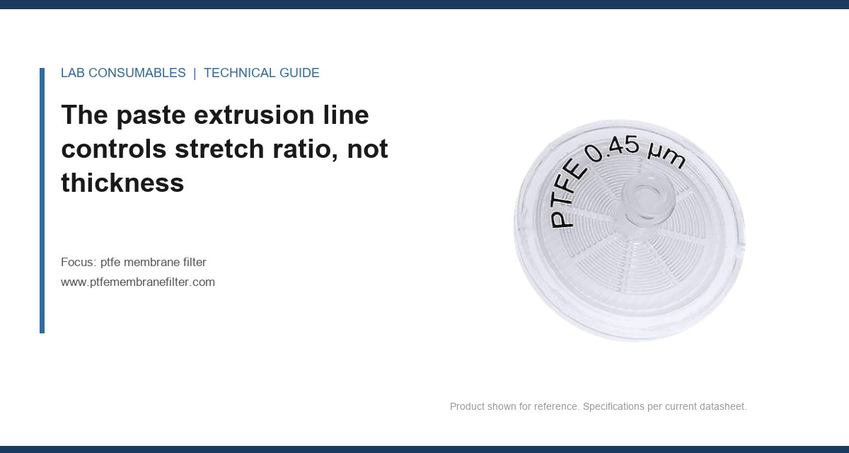
A line operator at a PTFE membrane plant in Jiangsu flagged a lot at 2:14 a.m. The bubble point had drifted from 0.138 MPa to 0.121 MPa across six consecutive rolls. Not a single roll was out of spec yet, but the trend was enough to stop the line. That is what a factory actually controls: not just whether a roll passes, but whether the next roll will pass. If you want to understand how a ptfe membrane filter is manufactured and what the factory controls, you have to look at the line station by station, because most of the control happens before the membrane ever becomes a filter.
PTFE cannot be melt-extruded. It does not flow. The resin arrives as a fine powder with a particle size typically between 400 and 600 microns, and the factory mixes it with a hydrocarbon lubricant, usually Isopar G or a similar isoparaffinic solvent, at a ratio of 16 to 22 parts lubricant per 100 parts resin by weight. That ratio is the first real control point. Too little lubricant and the preform cracks under pressure. Too much and the extrudate sags after the die.
The mixed powder is compressed into a cylindrical preform at 2 to 4 MPa, then forced through a die at a reduction ratio between 50:1 and 200:1. The extrudate is a thin-walled tube or flat ribbon. Here is the part most buyers get wrong: the factory does not control the final membrane thickness at the extruder. It controls the stretch ratio, because the extrusion output is an intermediate. A 3.2 mm extrudate wall can become a 25 micron membrane or a 150 micron membrane depending on what happens next.
Closed-loop control at this station covers extruder barrel temperature (typically 35 to 50°C), die pressure, and screw or ram speed. These are PID-controlled. The operator does not adjust them by hand. What is only checked at the end of the station is the green extrudate density, which should fall between 1.5 and 1.9 g/cm³. That is a grab sample test, not an inline measurement.
Lubricant removal is a drying curve, not a timer
After extrusion, the lubricant must be removed before stretching. The extrudate passes through a multi-zone oven. The factory controls air temperature, airflow rate, and residence time. But the real control variable is the residual lubricant content, measured by gravimetric analysis on a sample every 30 to 60 minutes. The target is below 0.1% by weight before the stretch oven.
I have seen lines where the oven temperature was perfectly stable at 180°C and the residual lubricant still spiked to 0.4% because the exhaust filter was clogged. The airflow dropped. The temperature probe never moved. That is why a good factory measures the output, not just the setpoint. If residual lubricant stays above 0.2%, the membrane will develop pinholes during stretching, because the lubricant vaporizes locally and blows a hole through the expanding node structure.
Biaxial stretching turns a dense tape into a porous node-fibril network
The heart of PTFE membrane manufacturing is the stretch oven. The lubricant-free extrudate is heated to between 250 and 320°C, then stretched in the machine direction and the transverse direction. The machine direction stretch ratio is typically 3:1 to 10:1. The transverse stretch ratio runs 5:1 to 20:1. The product of the two ratios, the area stretch ratio, is what determines porosity, pore size, and airflow.
This station has the tightest closed-loop control on the line. The factory controls:
- Oven zone temperatures, usually three to five zones, each held within ±2°C
- Stretch speed in mm/s for each axis
- Stretch ratio, verified by encoder feedback on the tenter clips or roll speeds
- Line tension, typically 10 to 50 N per meter of web width
What is not closed-loop controlled is the pore structure itself. The factory cannot measure pore size inline. It measures the process inputs and then verifies the output on a sample. A roll is sampled every 100 to 500 meters, depending on the grade. The sample goes to the QC lab for bubble point, IPA flow rate, and thickness. If the bubble point drifts, the operator adjusts stretch temperature or ratio. That is open-loop correction with feedback delay. A good factory keeps the delay short and the sampling frequency high enough to catch a drift before it becomes a reject lot.
Why bubble point is the line’s primary feedback signal
Bubble point is the pressure required to push air through the largest pore of a wetted membrane. For a 0.45 micron PTFE membrane wetted with IPA, the expected bubble point is 0.09 to 0.14 MPa. For a 0.22 micron membrane, it is 0.14 to 0.21 MPa. For a 0.1 micron membrane, it runs 0.25 to 0.35 MPa. These numbers are not theoretical. They are what a factory uses to decide whether to keep running.
When the bubble point drops, it means the largest pores got bigger. That can come from a lower stretch temperature, a faster stretch speed, or residual lubricant. When the bubble point rises, the pores got smaller or the membrane densified. A factory that only checks bubble point at the end of the roll is gambling. A factory that plots bubble point on a control chart and responds to a six-point trend, like the Jiangsu line I mentioned, is actually controlling the process.
Sintering locks the node-fibril structure, and the dwell time is the hidden variable
After stretching, the membrane is held under tension and heated above the PTFE crystalline melting point, which is 327°C for virgin resin. Sintering temperatures run 340 to 380°C. The dwell time at peak temperature is usually 10 to 60 seconds, depending on membrane thickness and line speed. This station looks passive. It is not.
The factory controls oven temperature, line speed, and web tension during sintering. The output that matters is dimensional stability. An under-sintered membrane will shrink when it sees heat later, whether that is in an autoclave at 121°C or in a GC inlet at 250°C. A well-sintered PTFE membrane should show less than 2% shrinkage in the machine direction after 30 minutes at 150°C. I have seen under-sintered lots shrink 8% and pull away from the polypropylene support ring, which ruins the seal.
Dwell time is checked indirectly. The factory measures line speed and oven length, then calculates dwell. But oven length is fixed, so the real control is line speed. If a factory pushes line speed to increase output, dwell time drops, and the membrane may pass bubble point and thickness checks while still being thermally unstable. That is why a serious buyer asks for the shrinkage test result, not just the pore size certificate.
Lamination and support layer bonding is where many OEM failures start
Most PTFE membrane filters are not a bare membrane. They are laminated to a support layer, usually a nonwoven polypropylene or polyester scrim, to give the filter enough mechanical strength to survive handling, pleating, or installation in a housing. The lamination station applies heat and pressure to bond the membrane to the support.
The factory controls lamination temperature, nip pressure, and line speed. For a PTFE-PP laminate, the temperature is typically 130 to 160°C, just below the melting point of the polypropylene support. Nip pressure runs 0.5 to 2.0 MPa. Too much pressure crushes the membrane pores. Too little gives a weak bond that delaminates in use.
The output check is peel strength, measured by a 180-degree peel test. A good PTFE-PP laminate holds at 0.5 to 2.0 N per 25 mm width. Below 0.3 N, the membrane will separate from the support during pleating or when the filter is wetted and handled. Above 3 N, the lamination is too aggressive and the airflow has probably dropped because the pores collapsed.
One OEM I worked with received a shipment of 47 mm laminated discs that passed visual inspection. The first use was in a vacuum filtration manifold. The membranes bubbled and lifted off the support because the peel strength was 0.2 N. The root cause was a lamination nip that had drifted out of parallel. The factory had not checked nip alignment in six weeks. The fix was a shim adjustment and a peel test on every roll, not every tenth roll.
Disc cutting and cartridge pleating turn a continuous roll into a controlled part
Once laminated, the roll moves to converting. For disc filters, the factory cuts discs using a die press or rotary die. For cartridge filters, the membrane is pleated, then wrapped around a core and caged. This is where dimensional control becomes critical.
For a 25 mm disc, the cut diameter tolerance is ±0.25 mm. For a 47 mm disc, it is ±0.5 mm. A disc that is 0.3 mm undersized on a 25 mm syringe filter housing will bypass at the seal edge. The factory controls die sharpness, because a dull die tears the membrane instead of cutting it cleanly. A torn edge leaves loose PTFE fibrils that can shed into the sample. Die life is tracked by cut count. A tungsten carbide die cutting PTFE-PP laminate typically lasts 50,000 to 200,000 cuts before resharpening, depending on the laminate thickness and the die clearance.
For pleated cartridges, the pleat height, pleat count, and pleat pack density determine the effective filtration area. A 10-inch cartridge with a 0.45 micron PTFE membrane might have 60 to 120 pleats, each 10 to 14 mm high, giving 0.5 to 0.8 m² of membrane area. The factory controls pleat height with a pleating machine that folds the membrane over blades. Pleat height tolerance is ±0.5 mm. If the pleats are too tall, the outer cage crushes them. If too short, the effective area drops and the flow rate suffers.
The end-of-line check for cartridges is a diffusive flow test or a pressure hold test. For a 0.22 micron 10-inch cartridge, the diffusive flow at 0.1 MPa air pressure should be below 20 mL/min for a wetted membrane. A higher value means a defect: a pinhole, a cracked pleat, or a bad side seam. This test is done on every cartridge, not on a sample. That is the difference between disc production and cartridge production. Discs are sampled. Cartridges are 100% integrity tested because the cost of a failed cartridge in a sterile process is too high.
Side seam welding is the most common pleated cartridge defect
The side seam is where the pleated membrane pack is joined into a cylinder. The factory welds it using heat, ultrasonic energy, or a hot wedge. The control variables are weld temperature, weld speed, and clamping force. For a PTFE membrane with a PP support, the weld temperature is usually 180 to 220°C. Too cold and the seam leaks. Too hot and the membrane melts through.
The output check is a seam integrity test. The factory inflates the cartridge with air under water and looks for bubbles. A good seam holds 0.3 MPa without a stream of bubbles. I have seen a lot of 200 cartridges where 12 failed the seam test. The root cause was a worn ultrasonic horn that had dropped its output amplitude by 15%. The weld looked fine visually. Only the bubble test caught it.
Cleanroom assembly and packaging controls particulate and endotoxin load
The final assembly of syringe filters, capsule filters, and cartridges happens in a cleanroom. The class rating matters. For analytical filtration, a Class 100,000 (ISO 8) cleanroom is common. For sterile filtration or biopharma use, the factory runs Class 10,000 (ISO 7) or Class 1,000 (ISO 6). The factory controls air changes per hour, HEPA filter integrity, and personnel gowning.
The output that matters is particulate cleanliness. A 25 mm syringe filter used for HPLC sample prep should contribute fewer than 5 particles per mL above 10 microns when flushed with 10 mL of clean solvent. The factory tests this by flushing filters and counting particles with a liquid particle counter. This is a batch test, not an inline test.
Endotoxin control is a separate issue. PTFE is inherently low in endotoxins because it is a synthetic polymer, but the support layer, the housing, and the assembly environment can add endotoxin. For filters used in biopharma, the factory controls endotoxin by using depyrogenated components and testing the finished filter. The limit is typically below 0.25 EU/mL for a 10-inch cartridge. A factory that does not test endotoxin cannot claim a controlled biopharma-grade product.
What the factory cannot control inline, and what that means for your spec
Here is the honest part. A PTFE membrane factory cannot measure pore size distribution inline. It cannot measure IPA flow rate on every millimeter of the roll. It cannot detect a single pinhole in a 100-meter roll without testing the whole roll destructively. What it can do is control the process variables tightly enough that the output stays within a predictable band, then verify the output on a sampling basis.
That means the buyer’s spec is a contract about sampling and limits, not a guarantee about every square centimeter. If you need a filter where a single pinhole is unacceptable, you buy a cartridge that is 100% integrity tested, or you test every disc yourself. If you need a disc for routine HPLC sample prep, a factory’s AQL 0.65 sampling plan on bubble point and flow rate is usually sufficient.
| Control point | Closed-loop controlled | End-of-line checked | Typical target |
|---|---|---|---|
| Extrusion lubricant ratio | No (batch mix) | Grab sample density | 1.5-1.9 g/cm³ green density |
| Extruder temperature | Yes (PID) | No | 35-50°C |
| Lubricant removal | Yes (oven temp, airflow) | Residual lubricant by gravimetric | <0.1% by weight |
| Stretch ratio | Yes (encoder feedback) | Bubble point, thickness | Area ratio 15:1 to 200:1 |
| Sintering dwell | Yes (line speed) | Shrinkage test | <2% at 150°C for 30 min |
| Lamination bond | Yes (temp, nip pressure) | Peel strength | 0.5-2.0 N per 25 mm |
| Disc diameter | No (die dependent) | Dimensional check | ±0.25 mm for 25 mm disc |
| Cartridge integrity | No | Diffusive flow on every unit | <20 mL/min at 0.1 MPa for 0.22 µm |
| Particulate cleanliness | No (cleanroom environment) | Batch flush test | <5 particles/mL >10 µm |
Two field cases where the line control told the story
Case 1: HPLC syringe filters with variable recovery. A pharmaceutical QC lab reported that their 0.22 µm PTFE syringe filters were giving variable recovery for a hydrophobic API. The recovery ranged from 88% to 102% across filters from the same box. The measurement that identified the problem was a bubble point distribution test on 50 filters. The bubble point ranged from 0.16 to 0.28 MPa, which is far too wide for a 0.22 µm membrane. The root cause was a stretch oven where the transverse stretch speed was oscillating because of a worn tenter chain. The factory had not replaced the chain because the average bubble point was still in spec. The fix was a chain replacement and a tightened bubble point range of 0.18 to 0.24 MPa for that grade. If you are running HPLC methods with tight acceptance criteria, check the bubble point distribution, not just the average. A Ptfe Membrane Filter with a wide pore size distribution will give variable analyte recovery, even if the average pore size is correct.
Case 2: Cartridge filters failing after autoclaving. A biotech pilot plant bought 10-inch 0.2 µm PTFE cartridges for a sterile filtration step. The cartridges passed the factory diffusive flow test. After autoclaving at 121°C for 30 minutes, three out of ten cartridges failed the post-sterilization integrity test. The measurement that identified the problem was a thermal shrinkage test on the membrane before pleating. The membrane shrank 6% in the machine direction at 150°C. The sintering dwell time was 18 seconds instead of the required 35 seconds because the factory had increased line speed. The membrane passed bubble point and thickness, but it was under-sintered. The fix was to bring the line speed back down and add a post-sintering shrinkage test to the in-process checks. If your cartridges see autoclave cycles, ask for the shrinkage data. A filter that passes at room temperature can fail after heat exposure if the sintering was rushed.
Decision checklist for qualifying a PTFE membrane filter factory
- Ask for the bubble point control chart for the last three production runs, not just the certificate of analysis. Look for a range within ±15% of the target, not just a passing average.
- Confirm the sintering dwell time and the shrinkage test result. A factory that cannot tell you the dwell time is guessing.
- Check the lamination peel strength spec. Below 0.5 N per 25 mm is a delamination risk in use.
- For cartridges, confirm that 100% integrity testing is done on every unit, not on a sample. This is non-negotiable for sterile filtration.
- Ask how the factory handles a bubble point trend. If they wait for an out-of-spec result before adjusting, they are not controlling the line. They are sorting scrap.
- For HPLC sample prep, pair the filter choice with a Cod Vial that matches your autosampler, because the filter and the vial both sit in the same sample path and a mismatch in dimensions or cleanliness will show up as ghost peaks.
- If you are running an autosampler with limited sample volume, use a Vial Insert with the correct bottom geometry so the filtered sample is fully accessible to the needle.
- For high-throughput labs, a 2Ml Vial with a PTFE-lined cap is the standard pairing for filtered samples that will sit in the autosampler tray for hours.
When you are comparing factories, compare their control philosophy, not their brochure. A factory that controls stretch ratio, sintering dwell, and lamination peel strength will make a consistent membrane even if the raw resin lot varies. A factory that only checks bubble point and thickness at the end of the roll is sorting, not manufacturing. The difference shows up in your recovery data, your autoclave failures, and your filter-to-filter variability. For chromatography work, the practical reference points are the consumables specifications from Agilent and Thermo Fisher, which assume a filter with a tight pore size distribution and low extractables. For environmental methods, the U.S. EPA SW-846 methods assume a filter that does not add particulates or adsorb analytes. And for method development, the technical notes from Restek are useful for troubleshooting sample prep steps that involve PTFE filters.
The decision rule is simple: buy from a factory that can show you the process data, not just the final test data. If the only numbers they can produce are the ones on the certificate of analysis, you are buying a sorted product, not a controlled one. The difference costs you in failed runs, not in the purchase order.
References & further reading
Related resources from our lab consumables network:
- Ptfe Membrane Filter at ptfemembranefilter.com
- Cod Vial at codvial.com
- Vial Insert at hplcinsert.com
- 2Ml Vial at 2mlsamplevial.com
External references and standards: